Main Back Board (S722)
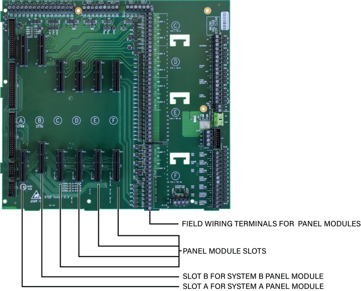
The Main Back Board of the XT+ Extinguishant Control Panel provides slots for required and optional panel modules, as well as for field wiring and power supply terminations.
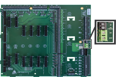
Minimum functions of the XT+ Extinguishant Control Panel are provided when Slot A of the Main Back Board contains System A Panel Module, Slot B contains System B Panel Module, and Slots C, D, E, or F contain a Dual Loop Panel Module. Two addressable loops are provided by the Dual Loop Panel Module in this configuration. The following figure illustrates the Main Back Board and the Power Supply of the cabinet box:
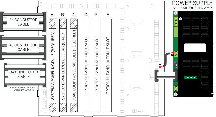
The Main Back Board contains connector slots A through F. Operation of the XT+ Extinguishant Control Panel requires that one Dual Loop Panel Module is connected in slots C, D, E, or F to meet minimum operating requirements.
The Dual Loop Panel Module can be connected in slots C, D, E, or F of the Main Back Board. Slot C of the Main Back Board is the factory location for the Dual Loop Panel Module connection.
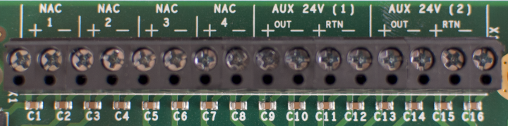
NAC and AUX 24V Terminals
NAC terminals 1 to 4 provide 24 VDC @ 2.5 A. In the default state, these circuits can be connected as four Class B supervised outputs. However, they can be configured as two Class A or two Class B and one Class A output. Power limited circuits should be routed separately from non-power limited circuits. The following figure illustrates the NAC and AUX 24V terminals of the Main Back Board:
|
Field Terminals |
Designation |
Supervision | Power Limited |
|---|---|---|---|
|
( + ) and ( - ) |
NAC 1 |
using EOL diode | Yes |
|
( + ) and ( - ) |
NAC 2 | using EOL diode | Yes |
|
( + ) and ( - ) |
NAC 3 | using EOL diode | Yes |
|
( + ) and ( - ) |
NAC 4 | using EOL diode | Yes |
|
OUT ( + ) and ( - ) |
AUX 24V (1) |
Supervision by connecting the end of the cable back to the RTN | Yes |
|
OUT ( + ) and ( - ) |
AUX 24V (2) |
Supervision by connecting the end of the cable back to the RTN | Yes |
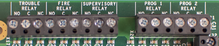
Terminals
The default designation is as shown below, however all 5 relays are user-configurable.
|
Field Terminals |
Default Operation |
Default Setting |
|---|---|---|
|
NO, C, and NC |
Trouble | |
|
NO, C, and NC |
Fire | |
|
NO, C, and NC |
Supervisory | |
|
NO, C, and NC |
PROG 1 RELAY |
Transparent |
|
NO, C, and NC |
PROG 2 RELAY |
Transparent |
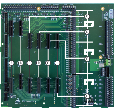
Panel Module Slots
The following figure illustrates the Panel Module Slots of the Main Back Board:
Field Terminal Assignments
Panel module slot positions on the Main Back Board correspond to specific field terminal locations on the Main Back Board.
|
Slot |
Field Terminal Location |
|---|---|
|
C |
Addressable Loops 1 and 2 |
|
D |
Addressable Loops 3 and 4 |
|
E |
Addressable Loops 5 and 6 or 8 Channel Relay. |
|
F |
Addressable Loops 7 and 8 or 8 Channel Relay, or Media Gateway |
Slots A and B do not contain corresponding lettering on field terminals of the Main Back Board. These slots are dedicated system boards that operate primary functions. System A Panel Module must connect to slot position A on the Main Back Board and System B Panel Module must connect to slot position B on the Main Back Board.
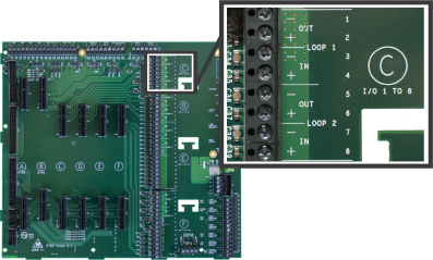
Panel Module Slots
Board Slot C
The following figure illustrates the Board Slot C terminals of loops 1 and 2:
| Field Terminals | Board Location | Function |
|---|---|---|
| 1-4 and 5-8 | Slot C | Loop 1 and Loop 2 |
Board Slot D
The following figure illustrates the Board Slot D terminals of loops 3 and 4: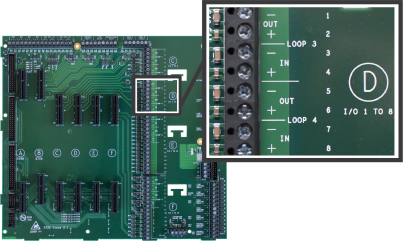
| Field Terminals | Board Location | Function |
|---|---|---|
| 1-4 and 5-8 | Slot D | Loop 3 and Loop 4 |
Board Slot E
The following figure illustrates the Board Slot E terminals of loops 5 and 6:
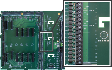
| Field Terminals | Board Location | Function |
|---|---|---|
| 1-4 , 5-8, and 9-16 | Slot E | Loop 5 and Loop 6 |
Board Slot F
The following figure illustrates the Board Slot F terminals of Loops 7 and 8:
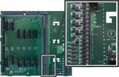
If you have, or plan to obtain, a Media Gateway Panel Module, it must be installed into Board Slot F.
| Field Terminals | Board Location | Function |
|---|---|---|
| 1-4 , 5-8, and 9-16 | Slot F | Loop 7 and Loop 8 |
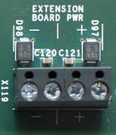
Extension Board Power Terminals
|
This figure illustrates Extension Board Power Terminals of the Main Back Board. These terminals are non-power limited.
These terminals are used for factory wiring purposes only. |
|
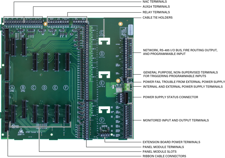
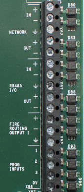
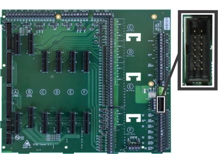
Network, RS-485 I/O, Fire Routing Output 1, and Prog Input
The following figure illustrates Network, RS-485 I/O, Fire Routing Output 1, and Prog Input of the Main Back Board:
Power Supply Terminals
|
Power Supply Terminals of the Main Back Board are used for factory wiring purposes only. |
|
|
Field Terminals |
Description |
Power Limited |
|---|---|---|
|
|
Ground terminal connection |
N/A |
|
TRBL |
Power trouble input. Active when connected to negative terminal ( - ). |
Yes |
|
( - ) |
Negative terminal connection from the 24V DC power supply |
Non-power limited |
|
( + ) |
Positive terminal connection from the 24V DC power supply |
Non-power limited |
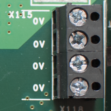
0V Terminals
|
This figure illustrates 0V terminals of the Main Back Board. These terminals provide general purpose 0V and are non-power limited. |
|
Power Supply Trouble Signaling Connector
| The following figure illustrates the Power Supply Trouble Signaling Connector of the Main Back Board. This terminal provides power and trouble signaling from the power supply. |
|
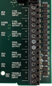
Supervised Input and Output Terminals
|
Fire and Trouble routing outputs provide supervised, 24V DC voltage with reversing outputs. Refer to Main Back Board Specifications for detailed information about these terminals. |
|